Flicker-free shutter glasses for full high-definition 3D viewing
Three-dimensional displays based on shutter-glasses offer full resolution, high-fidelity stereoscopic images. Left and right perspectives are displayed in a sequence on the same TV screen. Conventional shutter glasses use a liquid crystal (LC) cell enclosed between two polarizers to alternately block the left and right eyes from viewing the ‘wrong’ image so that the left image is viewed by only the left eye and the right image by only the right eye: see Figure 1(a). If the ambient light source is much brighter than the TV screen image, the viewer may perceive flicker.1 Another source of perceived flicker is artificial light sources, most of which emit light modulated at a high frequency. Although they are not normally perceived as flickering, interference between the light source modulation and the shutter switching can be perceived as a (lower) frequency flicker: see Figure 1(b).

In conventional shutter glasses, a pulsed voltage is applied to the LC cell and (via a microcontroller) synchronized with the TV set by an IR or RF signal. The shutter is opaque when the voltage is ON and translucent when the voltage is off. Since the light emitted by the LCD panel is polarized, the front polarizer facing the screen can be removed without loss of functionality: see Figure 2(a). However, omitting the front polarizer to improve flicker creates another problem. When the viewer's head is tilted, there is severe ghosting on the stereoscopic image caused by ‘crosstalk’ between the left and right images: the left eye receives some of the image intended for the right eye and vice versa. One way to overcome this is to apply a tilt-dependent voltage to the LC cell.
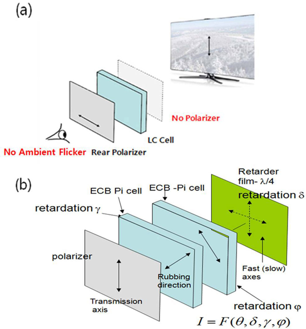

We found that a better design for the shutter replaces the front polarizer with a quarter-wave retardation film. This has fast and slow orthogonal principal axes. Incident light polarized parallel to either principal axis is unchanged, but incident light polarized between the axes is transformed to elliptically polarized light (circularly, if the incident light is polarized at 45° to each axis). We align the film's principal axis parallel to the transmission axis of the output polarizer. Replacing the front polarizer with the retardation film stops the flicker effect caused by bright ambient light. In addition, when the viewer's head is tilted, the tilted quarter-wave film causes elliptical polarization of the transmitted light that can be compensated by proper control of the off-state voltage applied to the LC cell. We add a tilt sensor to the shutter-glasses which sends information on the tilt to the LC cell's controller. Compensating for both right and left tilt requires a second LC cell: see Figure 2(b).
The shutter can be characterized by Io#/Ion, the ratio of its transmission in the off and on states. At low levels, the contrast ratio is practically equal to the stereoscopic crosstalk.2We measured the switching contrast Io#/Ion for a narrow beam of green LED light. Figure 3 shows the contrast ratio vs. tilt angle for a shutter, both with and without tilt compensation. During the measurement, we varied the tilt angle between −50° and +50°. At any given tilt angle, we adjusted the voltage applied to the compensation cell to minimize the shutter's transmission in the off state. The measured contrast ratio is 0.0062 with no tilt, and >1.1 with a tilt angle of +50°. A plot of the contrast ratios with and without active tilt compensation shows active tilt compensation results in lower crosstalk that does not increase much with tilt angle: see Figure 3. The contrast ratio varies between 0.0045 at zero tilt and 0.016 with ±50° tilt angle. The variation of transmission with tilt angle in the ON state is far less. We found experimentally that the full variation of open state transmittance within the same range does not exceed 10% in shutter with active tilt compensation.
In summary, we developed 3D shutter glasses that are flicker-free with respect to ambient light. They also can be tilted within ±50° without a significant increase in crosstalk. This is achieved by incorporating a tilt sensor and off-state voltage controller. Within the acceptable angle range of head tilt, crosstalk does not increase more than 1.6%, which frees the viewer to change their head position without adversely affecting the 3D image they see. We are now working to reduce the weight and power consumption of our shutter glasses, which currently weigh more and consume more power than conventional ones.
Dae-Sik Kim works at the Digital Media & Communication R&D Center.