Sub-nanometer interferometry for industrial high-precision metrology
Compact miniaturized optical sensors and actuators are required in several production technology applications, such as quality assurance, production measurement techniques, and non-tactile dimensional metrology. They are also used in space science applications such as gravitational wave sensing and drag-free attitude control, as for example in the satellite interferometry of the Laser Interferometer Space Antenna (LISA) space mission, proposed to detect gravitational waves from astronomical objects in the 10−4−10−1Hz frequency range.1 LISA will consist of three satellites acting as a Michelson-type interferometer with an arm length of five million kilometers. The plane circumscribed by the three spacecraft will constitute a very large gravitational antenna able to detect a passing gravitational wave by measuring the change in the length of the interferometer arms. In addition to high resolution and reliability, mass and physical dimensions are also relevant LISA design parameters. For instance, the translation and tilt measurements of the relative position of a free-floating proof mass with respect to spacecraft structure will have to be performed with a ∼5pm/ -sensitivity in translation and a ∼20nrad/-sensitivity in tilt. It is therefore anticipated that production technology sensor development will be able to benefit from advances achieved in such space applications. We summarize below our recent interferometer experimental results in the context of potential industrial applications.
Based on the optical readout design proposed for the proof mass position measurement aboard LISA satellites, we developed a highly symmetric heterodyne interferometer, which has measurement and reference beams with the same frequency and polarization.2–6 The optical path lengths of the measurement and reference arms are similar, especially inside optical components. For the tilt measurement, we utilize the method of differential wavefront sensing7–9 using a quadrant photodiode as the measurement diode. A schematic of our interferometer is shown in Figure 1 and a photograph in Figure 2.

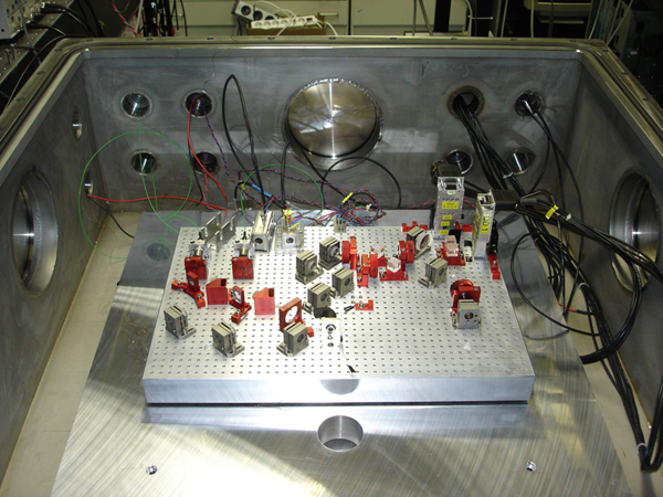
We use a commercial Nd:YAG non-planar ring oscillator laser at a wavelength of 1064nm. Approximately 200mW of its output power is split off for use in the interferometer. Each split beam is frequency-shifted using an acousto-optic modulator. Both resulting beams have a frequency difference of 10kHz, which is the heterodyne frequency of the interferometer. The beams are fiber-coupled and sent to the interferometer board which is placed in a vacuum chamber operated at pressures lower than 10−3mbar. Inside the chamber, part of the fiber output beams are split at a non-coated glass plate where the back surface reflections are directed towards monitor photodiodes (PD1 and PD2 in Figure 1) with the transmitted beams superimposed on a beat diode (PD3). The front surface reflections are sent to the differential interferometer and each beam is split into two parallel output beams using a symmetric beam separator cube. At a polarizing beamsplitter (PBS), the two beams of frequency f1 are reflected towards the measurement and reference mirror. Both beams are superimposed with the beams of frequency f2 at a non-polarizing beamsplitter (BS). The sum signals detected at two quadrant photodiodes provide the measurement (QPD1) and reference (QPD2) signals and can be used for the translation measurement. We implemented a digital in-quadrature phase readout utilizing a commercial field-programmable gate array board programmed with LabVIEW. The phase readout for the tilt measurement is similar, but in this case, the input signals are the signals from two opposing halves of the quadrant photodiode. In our design, we also incorporated intensity stabilization and phase locking of the heterodyne frequency at the fiber output. The measured noise levels are shown in Figure 3 for the translation measurement and in Figure 4 for the tilt measurement.

Adapting our interferometer to industrial applications

The interferometer consists of two parts: the optical setup for the generation of the heterodyne frequencies and the interferometer board itself, i.e., the sensor head. Both parts are connected via optical fibers and electric cables. While the optical setup requires a stable environment, the board also has to be provided with interferometric stability.
To address this issue, we first plan to realize a very compact and quasi-monolithic sensor head setup in which the baseplate will consist of a thermally stable ultra-low expansion glass material, such as Zerodur, with fused silica optical components connected to the baseplate via hydroxide-catalysis bonding.9,10 In a subsequent step, we will further decrease the size of the sensor head using micro-system technology based on integrated silicon optics. This should allow fabrication of a compact and robust sensor head suitable for nano-positioning control.
Three-dimensional profilometry and surface property measurements such as roughness, evenness, and roundness require a scan of the measurement beam over the surface of the material. For this purpose, we plan to implement a high-precision scan using a piezo-electric actuator in the measurement beam with a dynamic range of less than 100μm and a noise level below 1nm/. It will be realized using integrated micro-system technology with actuation implemented in either one or two dimensions. To overcome the limitation of the small dynamic range of the piezo-actuator, the sensor will be mounted on a three-axis coordinate measuring machine offering a dynamic range up to several meters and positional resolutions below 0.1μm. Combination with the precision scan will then transfer its high sub-nanometer resolution to the dynamic range provided by the coordinate measuring machine.
Thilo Schuldt studied physics at the University of Konstanz and at the University of Hamburg. He performed his MS work in the field of frequency-stabilized lasers. He is currently a PhD student at the Humboldt University of Berlin working for the University of Applied Sciences of Konstanz and for Astrium Ltd. in Friedrichshafen on high-precision laser metrology.
Martin Gohlke studied physics at the Humboldt University of Berlin and performed his MS thesis work in 2007 on the interferometer project described in this communication. He is currently a PhD student at the same university, and also with Astrium Ltd., pursuing his high-precision interferometry work for LISA.
Dennis Weise studied physics at the University of Konstanz where he also obtained his PhD in 2004, working in high-precision spectroscopy of ultracold molecules. He is now in at Astrium Ltd. as a systems engineer on the LISA team.
Achim Peters studied physics at the University of Cologne and at the University of Munich and obtained his PhD at Stanford University in atomic interferometry. After pursuing postdoctoral research at the University of Konstanz, he became a professor at the Humboldt University of Berlin in 2002, where he now leads the Quantum Optics and Metrology group.
Ulrich Johann obtained his PhD in physics in 1981 at the University of Bonn in laser and atomic spectroscopy. He was then an associate professor of physics at the University of Illinois in Chicago, and joined Dornier Ltd. (now Astrium Ltd.) in 1987. Since 2002, he has been head of the Science Missions and Systems division.
Claus Braxmaier has been a professor at the University of Applied Sciences of Konstanz since 2005. He studied physics and mechanical engineering and obtained his PhD at the University of Konstanz in laser metrology and fundamental testing methods in physics. Afterwards, he was responsible for systems at Astrium Ltd. in the Earth Observation and Science division.