Using spatial light modulators to measure laser beam quality
Two robust approaches using digital holograms programmed onto spatial light modulators provide fast and simple measurements of the laser beam propagation ratio.
Since its invention in 1960, the laser has been used in wide-ranging applications from medical eye surgery and industrial material processing to military targeting and microscopy in research. Most applications necessitate a high beam quality, meaning the beam must have a defined cross section and not diverge too rapidly. Because of its simplicity, the beam propagation ratio M2 is a very common and widely used parameter that summarizes the beam properties in one number.1 The International Standards Organization (ISO) sets the M2 definition and measurement instructions.2,3 The beam's intensity must be measured with a camera in various planes along the propagation direction, which is laborious and time-consuming. A plethora of techniques have been suggested to avoid the traditional propagation direction scan and enable faster evaluation of the beam's quality.4–9
The desired beam propagation can be achieved with digital holograms. A spatial light modulator (SLM) can manipulate an incident beam's phase and thus be used as a variable focal length lens (method A) or as a means of manipulating the beam's spatial frequency spectrum (method B). Both approaches enable the M2 value to be extracted without moving any components and with the potential for real-time measurements.10
Using the SLM for method A by displaying a spherical lens phase pattern, a camera can record a beam's curvature and diameter as a function of the focal length in a fixed plane behind the hologram. Thus, rather than probing one beam at several planes according to the ISO standard, we probed several beams at one detection plane. We were able to exploit the analytical formula that determines the beam's diameter for a variable focus lens and use it as a fit function, which yields M2 reliably and quickly.10
Using the SLM for method B, an optical field is propagated by Fourier transforming the field at the initial plane, multiplying the transfer function of free space, and then Fourier transforming it back.8, 11 We executed the necessary Fourier transforms optically using a single lens. The SLM displayed the transfer function of free space, so recording with a camera in a fixed plane behind the SLM yielded an artificially propagated beam. By hyperbolic curve fitting of its diameters, M2 can be determined according to the ISO standard.2 Figure 1 depicts the experimental setup used to measure the M2 from a laser source that is generally unknown. The setup is fairly simple, consisting only of the beam source, the SLM, a CCD camera, and a lens (only in method B), where all optical components remain fixed during the measurement.

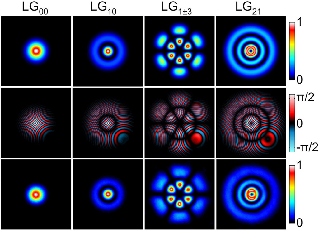
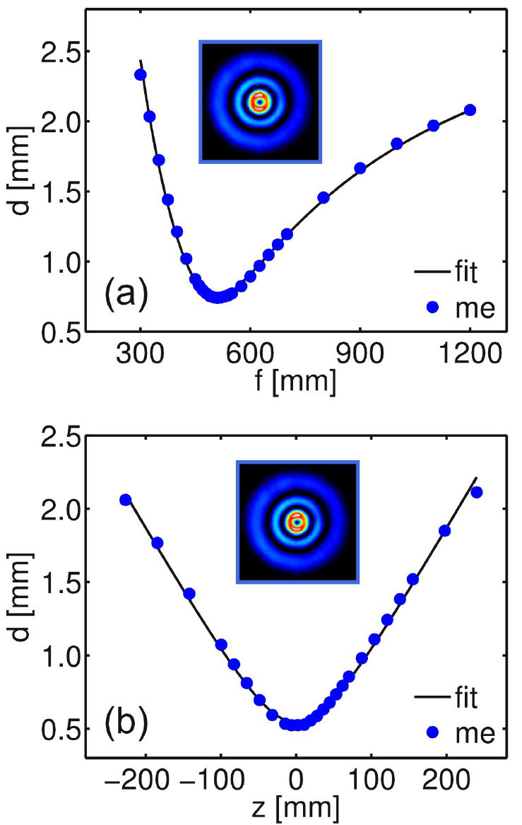
To test the two methods, we generated different Laguerre-Gaussian modes LGpl since their M2 is known to scale with the mode indices p and l according to M2=2p+l+1. The sample beams were produced by displaying the LG mode patterns using a special coding technique.12,13 Examples of beams with corresponding hologram patterns are shown in Figure 2. And Figure 3(a) depicts measured and fitted beam diameters as a function of the SLM lens focal length programmed for a Laguerre-Gaussian beam LG21 (method A). As can be seen, the measured diameters yield an M2 of 6.22, which is very close to the theoretical value of 6.0. Characterizing the same beam using method B—see Figure 3(b)—yields an M2 of 6.04 by ISO hyperbolic curve fitting.2 Table 1 summarizes the results for different LG modes and mode superpositions, comparing theoretical and measured M2 and showing excellent agreement.
| Mode | M2th | M2A | M2B |
|---|---|---|---|
| LG00 | 1.00 | 1.03 | 1.04 |
| LG01 | 2.00 | 2.01 | 2.09 |
| LG10 | 3.00 | 3.03 | 3.12 |
| LG0±4 | 5.00 | 5.25 | 5.05 |
| LG1±3 | 6.00 | 6.20 | 6.13 |
| LG21 | 6.00 | 6.22 | 6.04 |
In conclusion, we presented two approaches for fast and easy M2 measurements using digital holograms programmed onto an SLM. Method A uses the SLM as a lens of variable focal length, and method B uses it to manipulate the beam's spatial frequency spectrum to yield an artificial propagation. With the SLM frame rate of 60Hz, an M2 measurement time below one second is achievable. We attained M2 deviations of less than 5% by analyzing different Laguerre-Gaussian modes and mode superpositions of known M2, revealing a high measurement fidelity. Our next steps include generalization of the approaches to rotating beams and application to unknown laser sources, as well as comparisons to other ISO-conforming methods.
Friedrich Schiller University
Christian Schulze finished his diploma in physics in 2010 and is currently working toward his PhD. He is studying the modal characterization of fibers, fiber lasers, and laser resonators using computer-generated holograms.