Free-space optics technology improves situational awareness on the battlefield
Free-space optics (FSO), or optical wireless, is an unlicensed line-of-sight technology that uses modulated optical sources to transmit information through the air. By using light beams, FSO can transmit and receive data, voice, and video, providing data rates ranging from 100Mbps to 2.5Gbps. It can function over distances of several kilometers with a clear line of sight between the source and the destination. To maintain continuous line of sight and accurate alignment for high quality communications, FSO transceivers should be static. Thus, two essential challenges face FSO technology: first, severe weather conditions (fog, snow, etc.), and second, introducing mobility to this technology. If a reliable mobile FSO system can be achieved, the technology has excellent potential for scenarios requiring accurate situational awareness, such as battlefields.
The popularity of FSO has grown since the 1990s. The main focus was on solving the ‘last-mile’ problem in telecommunications: that is, the difficulty of providing high-speed access to information to distant users. The potential for FSO technology increases when mobility is added: many studies have been done to bring FSO strengths to mobile environments.1–3 The use of a spherical antenna3 covered with receiver modules has been demonstrated, using a small model train carrying transmitter modules—in that case, low-power light-emitting diodes (LEDs)—which moved on a 30cm-radius path around the antenna. The two modules did not remain aligned at all times, but when connectivity was lost, a new connection initialization algorithm was executed to promote alignment and re-establish communications. We introduce a tracking algorithm to maintain connectivity between FSO nodes on aerial and ground vehicles in battlefield scenarios.
In our theoretical approach, two scenarios are studied: an unmanned aerial surveillance vehicle, the Global Hawk, with a stationary ground vehicle, an M1 Abrams Main Battle Tank; and a manned aerial surveillance vehicle, the E-3A Airborne Warning and Control System (AWACS), with an unmanned combat aerial vehicle, the Joint Unmanned Combat Air System (J-UCAS). FSO nodes are mounted on gimbals—mechanical devices used to rotate an object in multiple dimensions—which are placed on each vehicle. The tracking algorithm sends steering commands to the gimbals as the vehicles move to maintain laser alignment. An overview of the first scenario, using the Global Hawk and M1 Abrams Tank, is shown in Figure 1.

The tracking algorithm specifies the gimbals’ angular positions and velocities while taking into account the effect of different conditions. Examining the algorithm in a 2D system illustrates its feasibility in a simple case, such as two cars traveling in parallel lanes and moving toward one another. Both the vehicles’ locations and attitudes are taken into consideration while calculating the angular positions and velocities for the gimbals. The algorithm is then applied in 3D systems (the two predefined scenarios). The vehicle's movement on the pitch, roll and yaw axes will also have a significant effect.

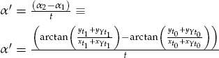
In the first scenario, the equations used to determine the angular position and velocity of the gimbals are as follows:

and


and

where x and y are the distances between the two vehicles on the x-axis and y-axis, respectively, at a certain time. Here, α is the angular position of the gimbals in the x-y plane, or in other words the yaw. The angular position of the gimbals in the z-y plane (or, in other words, the pitch) is θ, and z is the position of the vehicles on the z-axis. The other variables containing z also denote z-axis position, but affected by various forces: zP is the z-axis position of the vehicle affected by the change in pitch of the vehicle itself; zR, by the change in roll of the vehicle; and zY, by the change in yaw of the vehicle. yY denotes the y-axis position of the vehicle affected by the change in yaw of the vehicle itself, while t0 and t1 are the times for the vehicles at positions one and two, respectively. Finally, xY is the x-axis position of the vehicle affected by the change in yaw of the vehicle itself. Most of these parameters are determined by the use of a global positioning system (GPS), an inter-vehicular information system (IVIS), and an inertial navigation system (INS).

The second scenario addresses the use of the tracking algorithm for two aerial vehicles (AWACS and J-UCAS). The following equations are used to determine the angular position and velocity of the gimbals: 
and

also,

and
The divergence of the 1550nm laser source increases proportionally with the increase of the distance between the vehicles. This spread of the light helps determine the update rates of the systems. The update rates for a case where two vehicles are passing one another at maximum speeds and a separation distance of 13,700m are given for Scenarios 1 and 2 in Figures 2 and 3, respectively.
Mobility is the greatest challenge for FSO technology, and more complex studies will bring us closer to solving this problem. As we have shown, using the various positioning systems that are found in moving vehicles and gimbals, tracking can be achieved. Real-time video can be sent between aerial and ground vehicles in a battlefield using the high data rates provided by FSO technology, which can also be used in solving last mile telecommunications problems. Further refinement through research and testing will be done to prove the accuracy of this algorithm.
Mouhammad Al-Akkoumi is a PhD student in Electrical & Computer Engineering in the University of Oklahoma. He finished his Master's degree in Telecommunications Systems in May 2007. His interests lie in the fields of telecommunications, transportation, and wireless sensors.